Making a Checkbox
The IET recommends that the accuracy of a PAT instrument is checked regularly between calibration periods.
"The certificate verifies that the instrument was within calibration parameters at that time only. The certificate does not guarantee that the instrument is still fit-for-purpose at any time after that. In addition, it is recommended that the test instrument is checked at regular intervals." IET Code of Practice
Membership associations such as the NICEIC also require you to regularly check the accuracy of your PAT tester and will ask to see records of the checks during their annual visit.
Commercial checkboxes are available, but you can easily and cheaply make a checkbox yourself. You just need a few resistors to check the PAT instrument readings against.
For this checkbox we are going to use a 0.1 Ω resistor to check the earth continuity reading. The PAT tester we are using can carry out an earth continuity test at 25A, so we need to calculate a suitable power rating for the resistor.
Power = Voltage X Current (Joule’s law)
Voltage = Current X Resistance (Ohm’s law)
Rearranging these we get:
Power = Current2 X Resistance = 252 X 0.1 = 62.5W
Therefore we need a 0.1Ω resistor with a power rating of at least 62.5W.
If you have a battery operated test instrument, such as a Seaward Primetest or Kewtech EzyPat, the earth continuity test is carried out at 200mA, so the power rating isn’t an issue. It only needs to be rated at 4mW or above, so any 0.1Ω resistor would be okay to use.
To check the insulation resistance reading we are going to use a 1MΩ resistor. As the resistor value is high, the power rating shouldn’t be a problem. For a 500V insulation test:
Power = Voltage2 / Resistance = 5002 / 1,000,000 = 0.25W
Therefore any common ½W resistor will be okay to use here. It’s best to get the highest tolerance available, usually 5% (gold band), but 1MΩ resistors with a 1% tolerance are also available.

In this simple circuit we’ve included a switch and added two resistance values for the insulation test, 1MΩ and 2MΩ. As 2MΩ isn’t a common value, we’ve used two 1MΩ resistors in series to give us 2MΩ. The PAT instrument joins the line and neutral together for the insulation test, so we’ve used the neutral contact. Alternatively if you wanted to check the earth leakage, you could use the line. For example, including a 300KΩ resistor would give an approximate 0.75mA leakage. We could also go further and include additional test points and resistor values.
Parts:

- 0.1Ω 100W resistor
- 1MΩ ½W resistor (X3)
- Switch, SPDT
- Terminal post (test point)
- Plastic box
- Compression gland
- 1.0mm2 flex, 0.5m
- 13A Plug


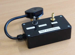

The completed the checkbox can be checked against a newly calibrated test instrument. In this case the measured insulation resistance values are 1.964 MΩ and 0.980 MΩ. The values are slightly off 2MΩ and 1MΩ due to the tolerance of the resistors used. This isn't a problem, we just label the checkbox with the measured values. The total cost of the DIY checkbox was £14.60. The 100W earth bond resistor was the most expensive component. As the earth bond test is usually only carried out for about 5 seconds, we could have probably got away with a cheaper 50W rated resistor. For a battery PAT tester, it would be even cheaper.
The accuracy of the tester can now be regularly checked between periods of calibration. Should the results waver by ±5 %, the PAT instrument should be re-calibrated.